
The surface of milling parts is nothing more than planes, plane contours, curved surfaces, holes and threads. The selected machining method should be adapted to the surface characteristics of the part, the required accuracy and surface roughness.
Analysis of surface machining plan
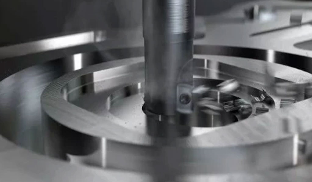
The only machining method for planes, plane contours and curved surfaces on boring and milling machining centers is milling. The rough milled plane, the dimensional accuracy can reach IT12~IT14 level (referring to the size between the two planes), and the surface roughness Ra value can reach 12.5~50μm. After rough and fine milling, the dimensional accuracy can reach IT7~IT9 level, and the surface roughness Ra value can reach 1.6~3.2μm.
Plane contour machining Plane contours are mostly composed of straight lines, arcs or various curves, and three-coordinate CNC milling machines are usually used for two-axis semi-coordinate machining.Machining of fixed bevel plane The fixed bevel plane is an inclined plane that forms a fixed angle with the horizontal plane, and the following machining methods are commonly used.
- When the size of the part is not large, it can be flattened with a swash plate; if the spindle of the machine tool can swing, it can be placed at an appropriate fixed angle and processed with different tools. When the size of the part is large and the slope of the bevel is small, the row cutting method is often used.
- For the surface of the round table and the oblique rib, it can generally be processed with a special angle forming milling cutter. The effect is better than that of using a five-coordinate CNC milling machine to process the swing angle.
There are two commonly used machining schemes for variable bevel surface machining:
- For the variable-bevel surface with small curvature change, a CNC milling machine with four-coordinate linkage of x, y, z and A is used, and an end mill is used to swing the angle by interpolation.
- For variable-bevel surfaces with large curvature changes, it is difficult to meet the machining requirements with four-coordinate linkage machining. Swing angle machining by arc interpolation.
Analysis of hole machining methods
There are drilling, expanding, reaming and boring. Large diameter holes can also be milled by circular interpolation.
- For the hole machining of the cast or forged blank hole with a diameter larger than φ30mm, the rough boring, half fine boring, hole chamfering and fine boring machining scheme are generally used. Milling program. When there is an empty slot, the saw blade milling cutter can be used to complete the milling after the semi-fine boring and before the fine boring. The boring tool can also be used for single-tool boring, but the single-tool boring efficiency is low.
- For the hole machining without blank hole with diameter less than φ30nnn, the plan of facing and flat end face, punching the center hole, drilling, expanding, hole chamfering, and reaming is usually adopted. The end face is punched in the center hole, half drilled, fine boring, hole chamfering, fine boring (or reaming) machining scheme. In order to improve the positional accuracy of the hole, it is necessary to arrange the countersinking and center hole drilling steps before the drilling step. The hole chamfer is arranged after semi-finishing and before finishing to prevent burrs in the hole.
- The machining of the thread is based on the size of the hole diameter. In general, the thread with a diameter between M6~M20mm is usually processed by the tapping method. For threads with a diameter below M6mm, the bottom hole is processed on the machining center, and the threads are tapped by other means. Because the energy-saving machine controls the machining state by tapping on the machining center, the small-diameter tap is easy to break. Threads with a diameter above M20mm can be processed by boring inserts.